
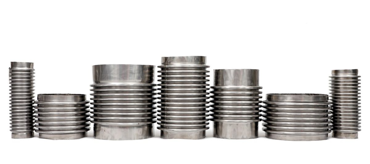
An expansion joint exists because pipe grows. Heat a hundred metres of austenitic stainless line from ambient to 300 °C and it will try to become roughly half a metre longer. Something has to absorb that, and if it is not an expansion joint it will be a nozzle, a flange or an anchor.
These are made to order, not picked off a shelf
Unlike a hose, every expansion joint is calculated for the specific bore, pressure, temperature and movement of your installation. Each order ships with its fatigue life, squirm stability analysis and spring rate, worked to EJMA 11th Edition and EN 14917:2021. That is why we ask more questions about a bellows enquiry than a hose enquiry.
Why stainless lines need more allowance than carbon steel
Austenitic stainless expands roughly 38 % more per unit length than carbon steel over the same temperature rise — 17.3 against 12.5 × 10⁻⁶/K. A movement allowance sized from a carbon-steel rule of thumb will be short on a stainless line. This is the single most common cause of under-specified expansion joints we see.
The eight configurations


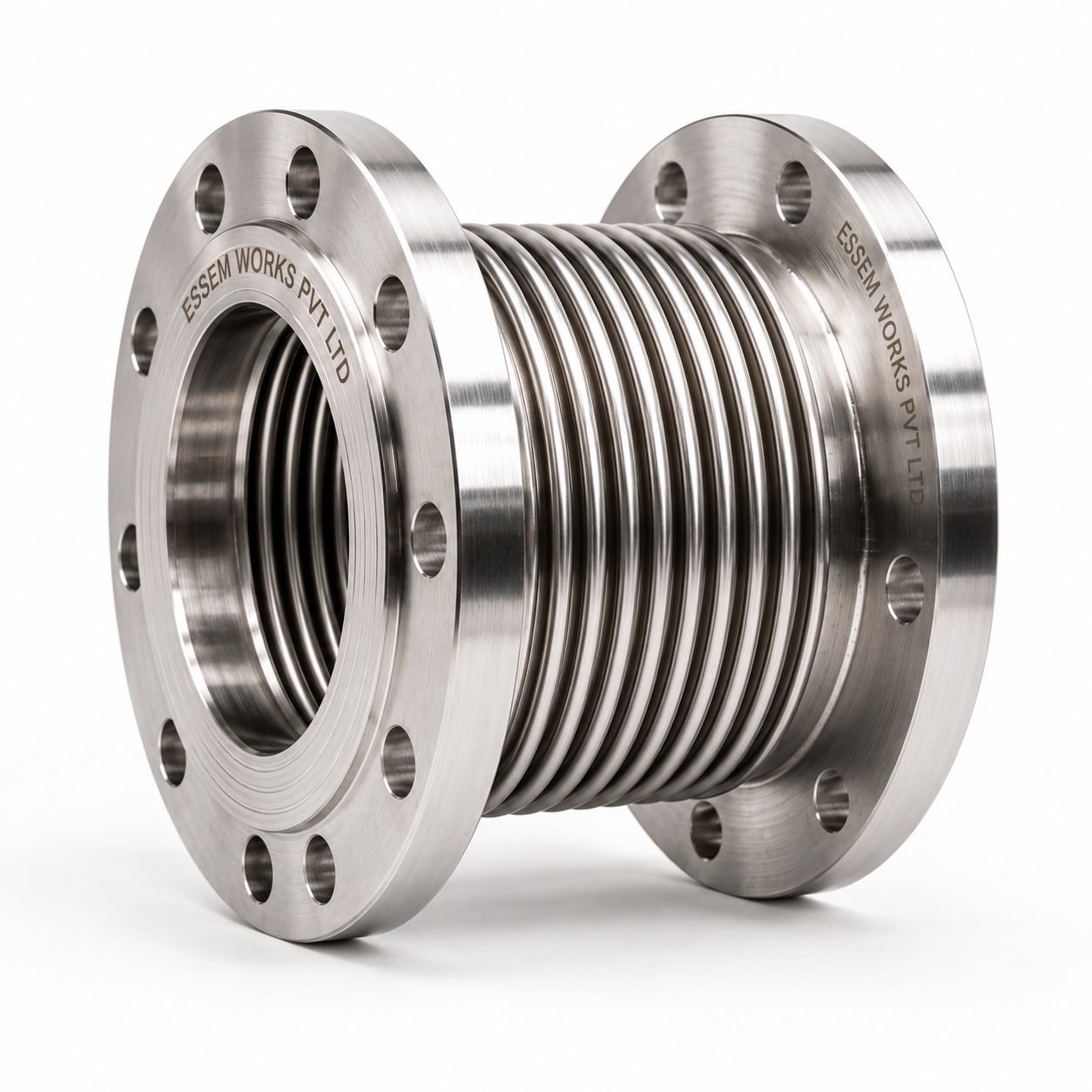
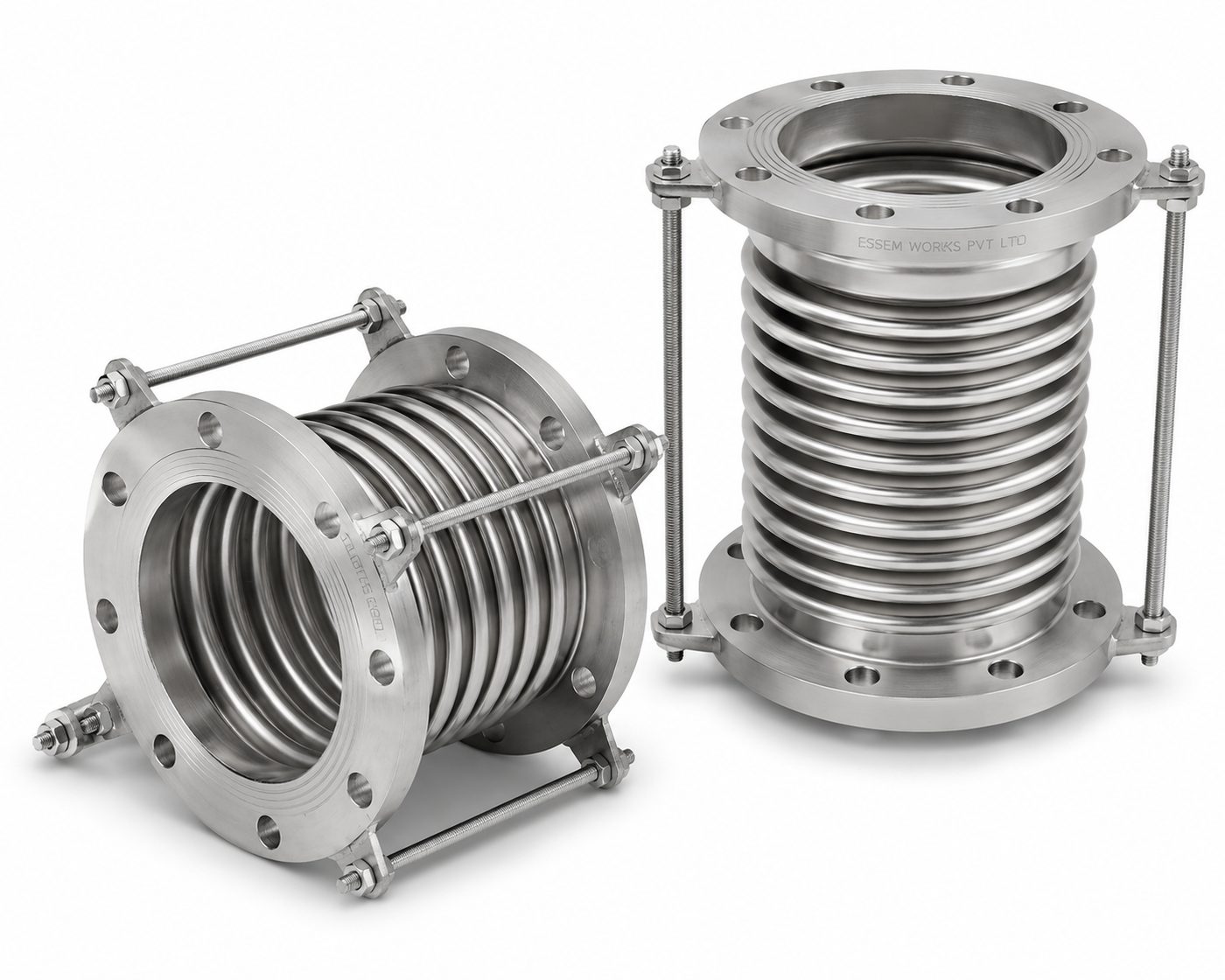
An expansion joint is a bellows plus hardware, and it is the hardware — tie rods, hinges, gimbal rings, pressure-balancing bellows — that decides which movements the joint accepts and, critically, where the pressure thrust goes. Choosing the configuration is the design decision; choosing the bellows is the calculation that follows it.
| Configuration | Movement absorbed | Pressure thrust | Typical application |
|---|---|---|---|
| Single bellows — axial, unrestrained | Axial compression and extension | Not contained — main anchors carry full pressure thrust | Single-axis thermal expansion in anchored, guided piping |
| Single bellows with limit rods | Axial; rods do not restrict normal movement | Not contained in normal operation — rods act only as safety stops if an anchor fails | Guided runs where anchor-failure protection is required |
| Tied single bellows | Lateral and small angular only — axial locked by the rods | Contained — tie rods continuously carry full thrust | Pump and equipment connections without main anchors |
| Hinged — single-plane angular | Angular rotation in one plane | Contained, through the hinge hardware | Used in pairs or triples for large lateral offset |
| Gimbal — multi-plane angular | Angular rotation in any plane | Contained, through the gimbal ring | Omni-directional rotation at pipe bends |
| Universal — dual bellows with control rods | Axial, lateral and angular | Not contained — control rods only distribute movement between the two bellows and never carry thrust. The tied-universal variant does carry thrust, lateral only | Complex pipe movements, large lateral deflection |
| Pressure-balanced, in-line | Axial and lateral | Contained by the balancing chamber; no main anchors needed | Turbine, compressor and equipment nozzle connections |
| Pressure-balanced, elbow | Axial and lateral at a change of direction | Contained by the balanced chamber at the elbow | Removes thrust from anchors at elbows |

Pressure thrust — the force people forget

A bellows is a flexible element in a pressurised line, so pressure acting on its effective area produces an axial force that tries to push the line apart. That force is often far larger than the weight of the pipe, and it does not go away because it was not calculated.
Ft = pressure thrust force (N) p = internal pressure (N/mm²) Aeff = effective area (mm²), taken at the mean convolution diameter
Three ways to deal with it. Design the anchors to take it — correct, and often expensive. Tie the joint so the rods carry it — correct, and it removes axial capability. Or use a pressure-balanced design that cancels the force internally — correct, and the right answer at a sensitive nozzle where the equipment simply cannot accept the load.


Multi-ply construction


Our bellows are formed as multiple thin plies rather than one thick wall. Splitting the pressure-bearing wall into several thinner layers raises movement capability substantially without giving up pressure resistance, because bending stress in a thin ply is far lower than in a thick one at the same deflection. It also means the plies can be different materials — a corrosion-resistant inner ply against the medium, more economical material outboard — and the space between plies can be monitored for leakage.


Anchors, guides and squirm


An expansion joint does not work on its own. It works as part of a system that includes the anchors that define where the pipe is not allowed to move and the guides that keep it aligned. Get the guiding wrong and a bellows under pressure will buckle sideways — squirm — which is a sudden failure, not a gradual one. Guides go close to the joint and at defined intervals beyond it.
Core specifications
| Parameter | Value |
|---|---|
| Nominal diameter | DN50 to DN3000 |
| Bellows materials | SS 304L / 316L standard · SS 321, Alloy 625 (UNS N06625), Alloy 825 (UNS N08825) to order |
| End fitting materials | Carbon steel, SS 304 / 316, precision-cast and forged alloy fittings |
| Connections | Plain weld ends (ISO bevel) · EN 1092-1 flanges · ASME B16.5 flanges · RTJ |
| Design pressure | Full vacuum to 50 barg standard; higher with engineering review |
| Temperature | −196 °C to +900 °C, material-dependent; higher with internally insulated or refractory-lined designs |
| Convolutions | Single-ply or multi-ply laminated |
| Hydrostatic test | 1.5 × design pressure (EJMA / ASME practice). Where the project requires CE marking to EN 14917 under the Pressure Equipment Directive, tell us at enquiry and we will confirm the conformity assessment route before quoting |
Design basis and standards
| Standard | What it governs |
|---|---|
| EN 14917:2021 | Metal bellows expansion joints for pressure applications — the European design and testing standard our joints are designed to |
| EJMA, 11th Edition | Expansion Joint Manufacturers Association standards — the movement, stress and fatigue methodology |
| EN 13445 / EN 13480 | Unfired pressure vessels and metallic industrial piping, where the joint forms part of that scope |
| ASME B31.1 / B31.3 | Power piping and process piping, where the project specification calls for them |
All four descend from the same underlying stress model, so a joint designed correctly to one is not a different object from a joint designed to another — but the acceptance criteria and the documentation differ, so tell us at enquiry which code the project runs under.
When the bellows needs an internal liner
A flow sleeve inside the bellows stops the flow hitting the convolutions directly. It extends fatigue life and smooths the flow. Per EJMA guidance, fit one when any of these is true:
- Gas, steam or air — velocity above 1.2 m/s per 25 mm of bore up to DN150, or above 7.6 m/s beyond DN150
- Water or liquids — velocity above 0.6 m/s per 25 mm of bore up to DN150, or above 3 m/s beyond DN150
- An elbow, tee or valve within ten pipe diameters upstream — multiply the actual velocity by four before applying the limits above
- The medium is abrasive, particulate or slurry, or it is high-temperature steam or gas injection

Materials
| Element | Standard | On request |
|---|---|---|
| Bellows | SS 304L (1.4307), SS 316L (1.4404) | SS 321, Alloy 625 (UNS N06625), Alloy 825 (UNS N08825) |
| Flanges and weld ends | Carbon steel, SS 304 / 316L | To project specification |
| Hardware — tie rods, hinges, lugs | Carbon steel, SS | Coated to the project corrosivity category |
| Liner | SS 321 / 316L | Interlock hose liner for hot gas duty |